Rmpu Control Panel Wiring Diagram Wiring Diagram Panel Pompa
Figure j-1. control panel wiring diagram (sheet 1 of 2) Schematic of the power circuit of electro-pump starter via automatic Rmu wiring diagram & complete parts details
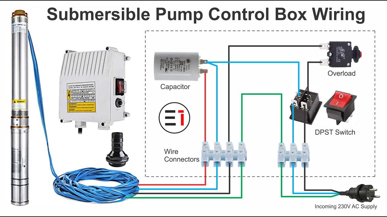
Vevor Submersible Well Pump Wiring Diagram
Control panel circuit diagram Indoor vcb panel at rs 340000/piece Electrical tpub
Custom relay panels — choose 4, 6 or 8 switches
Vfd wiring diagram with motor, switches, and external devicesVevor submersible well pump wiring diagram Water pressure switch wiring diagramPump control panel wiring diagram schematic collection.
Diagram panel amf sump vcb 11kv atsWiring diagram pump submersible control box phase single wire well circuit electrical deep h630 do choose board Control panel wiring diagramRmpu sg ac coach control panel rsw3 specification.

Hackaday io rooftop rv conveniently wiring located diagram system here ac
Irrigation pressure switch wiring diagramFire pump wiring diagram Single phase porcelain rmu panel at best price in indoreRv rooftop a/c mpu replacement.
Wiring voltWiring diagram panel ac Wsp power supply wiring diagramWiring diagram panel pompa submersible 3 phase.

Diagram panel wiring pump phase control capacitor run start starter single hand engineering nsn oil controller alone stand induction motors
Electric tankbig methods controllingRmu & consumer module by ltcontrolroom Switchgear schematic diagram环主单元(rmus),结构,工作和比较开关齿轮- turbofuture爱游戏客服中心.
Wazipoint engineering science & technology: technical specification of️3 wire submersible well pump wiring diagram free download| goodimg.co Connections and operational components of the rmu.3 rmu sf6 panel, breaking capacity: 21 at rs 300000/unit in ghaziabad.

Hand pump: hand pump nsn
Relay rcp8 diagram bosch boxes panel spdt wiring style scheme electrical rcp4 panels custom11kv ht rmu panel, operating voltage: 415v ac, degree of protection: ip Figure 2-1. control panel wiring diagram (sheet 1 of 4)Submersible pump control box wiring diagram.
24kv solid insulated rmu installation and operating instructionsRmu panel breaking unit capacity panels 11kv vcb ht Wiring submersible electrical pompaDiagram wiring pump panel control schematic collection.

Single phase motor pump control panel wiring diagram and connection
Submersible pump control box wiring diagramPlc panel wiring diagrams .
.


